Mostly invisible, yet essential, camera work is key to any game with dynamic cameras. This article dissects a concise Unity open source library which dynamically keeps a set of objects (e.g. players and important objects) in view, a common problem for a wide range of games.
The library was developed for, and used by my first Steam game, Survival Ball. The game has an heavy shared screen local co-op component, which requires the camera to dynamically keep many key elements in view.
There are good camera resources for Unity, but I found them to either do too much or too little for this specific problem, so I thought this could be a good opportunity to learn a bit more about dynamic camera movement and to share that knowledge and code with the community.
Overview
The library is fed with the desired camera rotation (pitch, yaw and roll), the target objects that will be tracked and the camera that will be transformed.
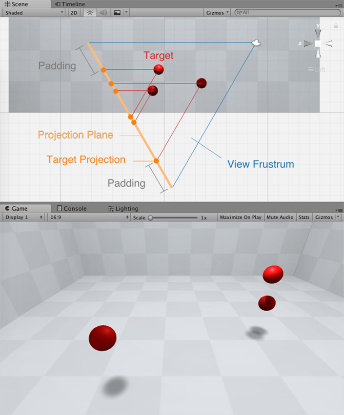
The library’s sole responsibility is to calculate a camera position in which all targets lie inside its view. To achieve this, all target objects are projected onto a slice (plane) of the camera’s view frustrum. The projections located inside the view frustrum will be visible and the others will not. The idea is to trace back a new camera position from the outermost target projections, since this way we are guaranteed to include all projections inside the view.
In order to make the bulk of the operations easier to compute, the process starts by multiplying the camera’s inverse rotation with each of the targets positions, which will place them as they would if the camera’s axis would be aligned with the world’s axis (identity rotation). Once the camera position is calculated in this transformed space, the camera rotation is multiplied by this position, resulting in the final desired camera position. The actual camera position is then progressively interpolated towards this desired position, to smooth out the camera movement.
Implementation
Most of the operations are performed in the transformed space where the camera’s axis would be aligned with the world’s axis (identity rotation). After the targets are rotated into the camera’s identity rotation space by multiplying the camera’s inverse rotation with each of the targets positions, the first task is to calculate their projections.
Please note that in all the figures below (with the exception of the horizontal field of view angle section), the camera is present for reference only, as its final desired position will only be uncovered in the final step.
Targets projections
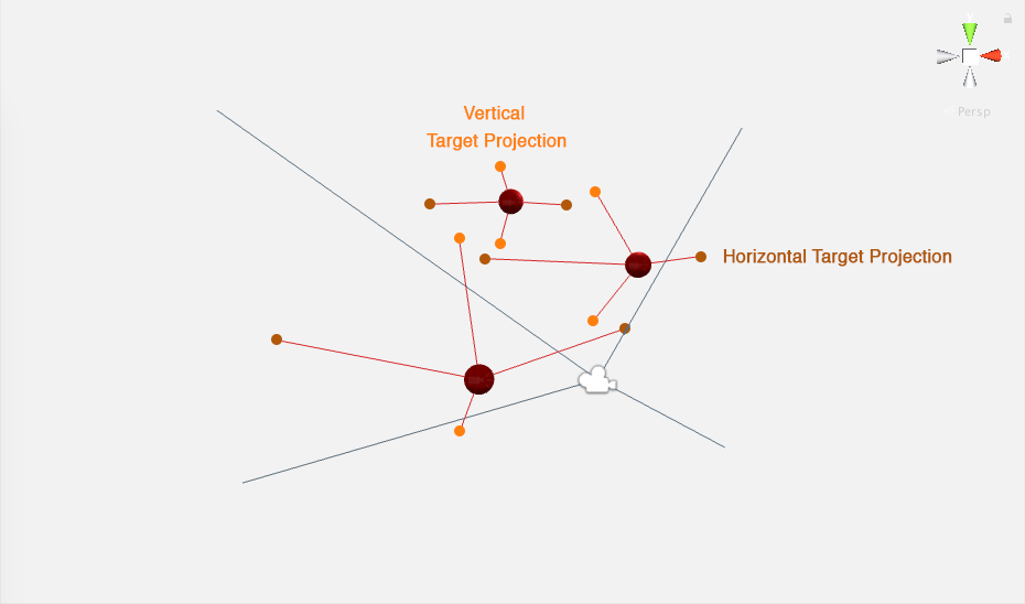
For each target, four projections are cast to a plane parallel to the view plane, sliced from the camera’s view frustrum. The line described from the target object to its respective projection is parallel to the camera’s view frustrum edges. Relative to the camera, two of these projections run horizontally, and the other two vertically.

If any of the target’s projections are outside the camera’s view frustrum (or its sliced plane), then the target object will not be visible. If they are inside, the target object will be visible. This means that the four outermost projections from all targets will define the limit of where the view frustrum must be in order to have all objects in view or partially in view. Adding some padding to these outermost projections (i.e. moving these projections away from the center of the view frustrum plane slice), will result in additional padding between the target object and the camera’s view borders.
Vertical projections
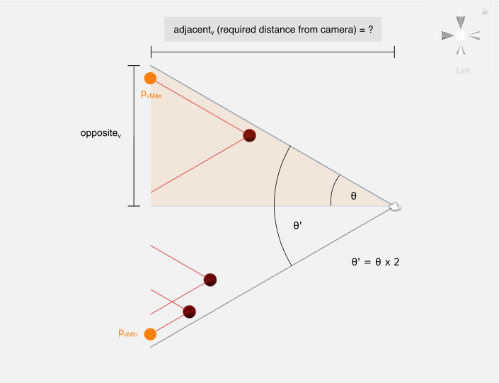
For all vertical projections positions, we are interested in finding their Y component. In the figure below, notice the right triangle with one vertex on the target object and another one on the projection. If we discover the length of the side running parallel the projection plane, that value can be added to the Y component of the target’s position, resulting in the Y component for the upper projection.
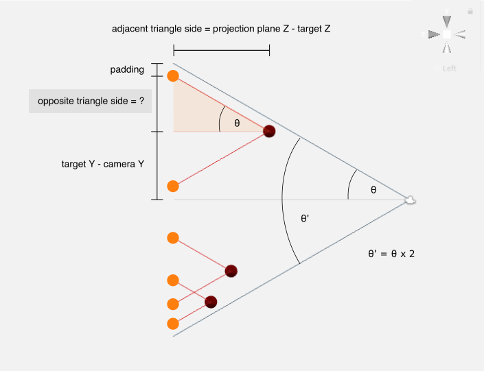
θ is equal to half the camera’s vertical field of view angle θ′ (θ=θ′2). The vertical field of view angle θ′ is provided by the camera’s fieldOfView in degrees, which needs to be converted to radians for our purposes (θ′=θ′degrees×π180º).
The triangle’s adjacent edge length (relative to θ) is known, thus we can find the length of the opposite side of the triangle by using trigonometric ratios.
opposite=tan(θ)×adjacentWith this, the upper projection’s Y/Z components can be fully calculated. The bottom projection has the same Z component as the upper one, and its Y component is equal to the target’s Y component minus the calculated opposite triangle edge length.
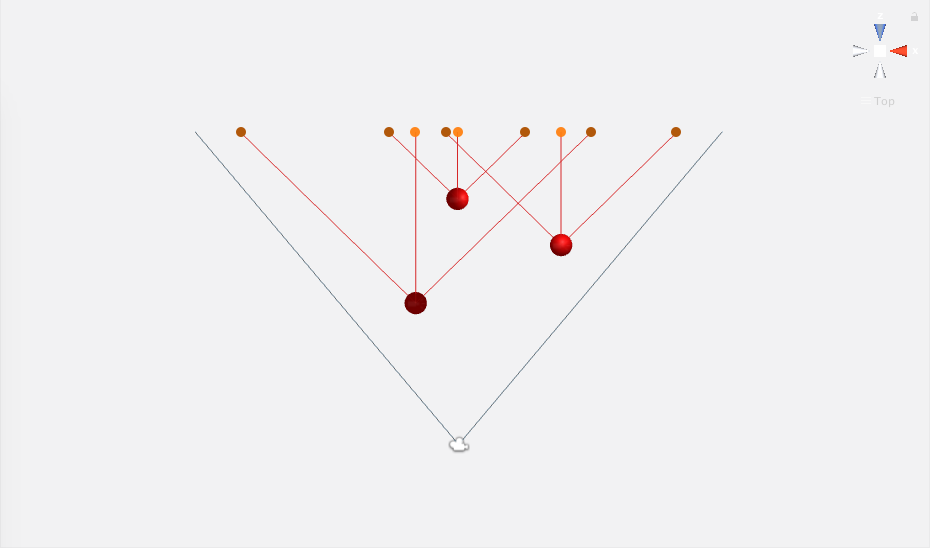
Horizontal projections
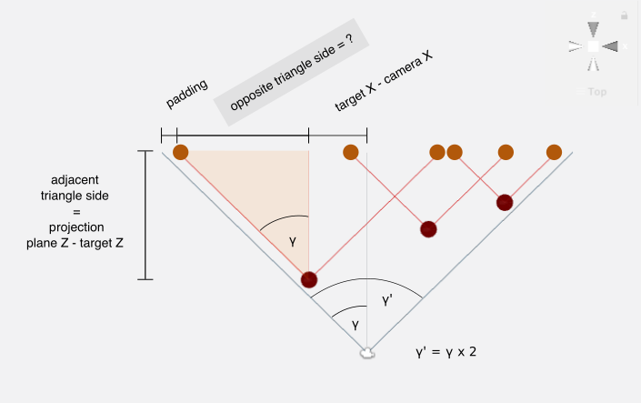
The horizontal projections follow a set of similar set of calculations, difference being that we are now interested in finding the X component (instead of Y), and the horizontal field of view angle is used instead of the vertical one. The horizontal field of view angle γ′ and its half value γ (γ=γ′×2) need some further steps to be computed, which will be detailed in the following section.
Horizontal field of view angle
Consider the following figure, in which γ represents half the horizontal field of view angle, θ represents half the vertical field of view angle, w the viewport width and h the viewport height:

Using trigonometric ratios, these two equations can be devised:
{tan(γ)=w/2adjadj=h/2tan(θ)Replacing adj in the first equation with the definition of the second one:
tan(γ)=w/2h/2tan(θ)⇔tan(γ)=w/2h/2×tan(θ)⇔tan(γ)=wh×tan(θ)⇔γ=arctan(wh×tan(θ))Unity’s camera has an aspect attribute (view canvas width divided by height, i.e. aspect ratio=wh), with which we can finalize our equation and discover the horizontal field of view angle half value.
Outermost projections
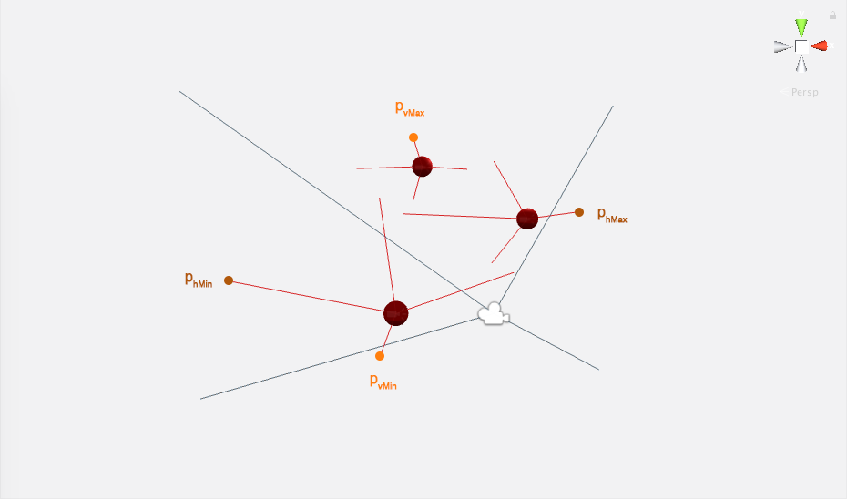
Having all target projections calculated, the four outermost ones are picked:
- phMax is the projection with the highest X component
- phMin is the projection with the lowest X component
- pvMax is the projection with the highest Y component
- pvMin is the projection with the lowest Y component
Calculating the camera position
In the transformed space
The X and Y components of the desired camera position in the transformed space are the midpoints of their respective outermost projections, this is, the midpoint between phMax and phMin is the camera’s X position, and the midpoint between pvMax and pvMin is the camera’s Y position.
The Z component of the camera position in the transformed space is calculated by backtracking a view frustrum from the the outermost projections to the camera Z component candidate. The furthest Z component from the projection plane will be the chosen, in order for the final camera position to contain all targets within its view.
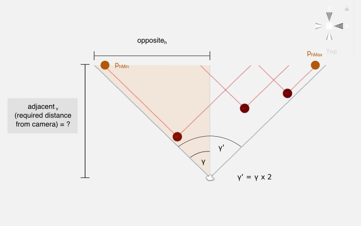
Once again, trigonometric ratios will be used to calculate these Z position candidates.
adjacentv=oppositevtan(θ)adjacenth=oppositehtan(γ)The highest value between adjacentv and adjacenth will be picked for the camera’s Z position component in the transformed space.
Final camera position in the original space
With the camera position calculated in the transformed space, we can now multiply the desired camera rotation with this position, which will provide us with the final desired camera position. The actual camera position is then progressively interpolated towards this desired position, to smooth out the camera movement.
Where to get it
The library is available on GitHub and the Unity Asset Store. An example scene of the library’s usage is included. Feedback is most welcome and I hope this can be useful!